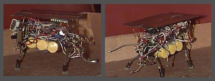
This page contains circuit diagrams and code for a walking robot I made using Mark Tilden's nervous network along with my own tinkerings like the reverser and brain circuits. Construction is a bit odd, chips with pins bent flat with wirebits and parts in-the-air within about a 1.2" by 1.5" by 2" space with a gearmotor at either end, a cordless phone battery slung underneath and feelers made from guitar strings. The whole thing is about 4" long, not including feelers, with a leg-span about 3" spacing and width. It can climb about 1/2" and doesn't do well on carpet.
A little evolution... WALKER.TXT contains various two-motor walker circuits I devised. The first microcore I made (without motors) used a '245 chip for a motor driver, this walker never got made because my motors draw too much for it to power. The design that actually got made used transistor pairs to drive the motors. The circuit started out as a more-or-less stock micro-core circuit except for the transistors but I quickly realized the importance of being able to back up. The obvious solution would have been a relay to swap the wires on one of the motors, however 3 volt relays are kind of hard to find and relays in general are power hogs. I tried using an analog switch chip to swap the driver signals, but the 4016 chip has too high of an on-resistance to drive the drivers (bet a 4066 would have worked and the design would be very different right now). Then I thought, just make the pulse go backwards. I ended up using two 4016 chips each wired as a two-wire crossing circuit. This walker was pretty good and would back away from obstacles in its ways.
[ Since this walker was made, I've discovered that stacked 74HC245 chips (or 74HCT245 as I used) work much better for motor drivers than complementary transistor pair drivers. The lower drive requirements of the chips make the reverser circuit simpler, and the '245 has an enable input that keeps the legs from twisting out of shape when initialized. The transistors do give the microcore more feedback, if the 1.3 volts loss isn't a problem, but be sure the transistors can handle the motor current. True transistor H-bridges don't have the loss problem but the threat of "smoke" has kept me from using them. See Another Nervous Net Walker for a circuit using the '245 chips. The design here is a good design if you desire lots of "feedback" and don't mind the loss, but if building for the first time, don't try to make this but use the much simpler new circuit. This isn't here for people to make anyway, but to document this particular robot - if you make it as-is you'll be copying my less-than-efficient design decisions which may or may not matter. ]
NOTE: The diagrams include a version of the Nervous Network, invented and internationally patented by Mark Tilden. Commercial usage is prohibited unless arrangements are made with the patent holder <mwtilden@lanl.gov>.
Mechanical...
                                    ____________
   Rear Motor  __________ _________:  PIC brain :
        ____  : Reverser : Drivers :____________:  .-- Front Motor
     :-|    | :__________:_________:____  .-' \ <-'______  (angled)
     : |    | : Microcore / Nu neurons  : \    \  :Photo :
     : |____| :_________________________:  \   _\ :______:
     :.|....|..............................:..'..\...S---------O Side
     : |____| :   .--------------------.   : \_.-'   `.           Feelers
     :   ||   :  /                      \  :    \\    :   Front    (2)
     :   <>   : |   Cordless Phone       | `.    <>   : S  Feeler
     :   ||   : |   (NiCad) Battery      |   `.   \\  :  \
     `........'  \                      /      `......'   \
         ||       `--------------------'            \\     \____|
         ||                                          \\
         ||                                           ||
         ||                                           ||
        |__|                                         |__|
Topology...
  Feel L   Front   Feel R
     -\     +|      /-
       \     `-----/--.
        \  photo  /  Nu-     ->- = diodes
         :  L R  :    :      M   = motors
         :  : :  *->--:      1-4 = Nv neurons (C input, R to gnd)
         *--:-:--:->--:      Nu+ = pos. neuron (C to gnd, R to +)
       ..:..:.:..:..  `-<-.  Nu- = neg. neuron (R to gnd, C to +)
    .--:  'brain'  :----<-:
    :  :...........:      :    Neurons made from 74HCT14 chip
    :   :: + M - ::       :    Reverser made from 2 CD4016 chips
    :   :`-2   4-':       :    Brain made from PIC16C56 and 24C65
    :   :  |\ /|  :       :
   Nu+  :  | \ |  :  .....:......
    :   :  |/ \|  :  : Reverser :  Forward: 1-->2-->3-->4-->1
    `->-`--1   3--'  :..........:  Reverse: 4-->3-->2-->1-->4
           + M -
Walker circuit...
          +
          |
       Npn >|-----.    Rev.Clr<--.         .---|>|--*- +  .-< Reset
          |e.---. |              |     /|  | .----. |     |          Reset
   .------*-|470|-*--------.     *---O< |--*-|1.5M|-'     |          Switch
   |      |e`---' |        |     |     \|  | `----'   .---*----------O|_
   |   Pnp >|-----'        |     |  2.2u   | .----.   |         +    O| \
   |     _|_     .---|<|---|-----'  .--||--*-| 10 |---'         |   _|_
   |             |         |       _|_       `----'     .-----|< Npn
   |        .12u |1  |\    |         .12u  2  |\        | .---.e|
   |      .--||--*---| >O--*---.   .--||--*---| >O---*--*-|470|-*-----.
   |      |     _|_  |/        |   |     _|_  |/     |  | `---'e|     |
   |      |    |1.5| 74HCT14   |   |    |1.5|        |  `-----|< Pnp  |
   |      |    |_M_|           |   |    |_M_|        |         _|_    |
   |      |     _|_            |   |     _|_         |                |
   |      |                    |   `------.          |  Motors..      |
   |      | CD4016 by 2    .---|----------|----------'  MPJA 8679-MD  |
   |      |     .----------|---|----------|-.           3V 30 rpm     |
   |      |   .-|-*-|><|---*F  `-*-|><|---*F|        +                |
   +      |   | *-|--'     |     |    `---|-*       _|_               +
 Rear      \ /  | `-|><|-. |R    `-|><|-. |R|      |100|            Front
 Motor      \   |     `--|-|-*------'   | | |      |_K_|  +         Motor
   -       / \  | .-|><|-|-'R|   .-|><|-|-'R| .----. |   e|           -
   |      |   | | |   `--|---*---|--'   |   *-|220K|-*--|< Pnp        |
   |      |   `-|-*-|><|-*  F|   *-|><|-*  F| `----'      |           |
   |      |     `----' ` |   |   |    `-|---*------.      |           |
   |      |        .----.`---|---|------|----------|-.    |     +     |
   |      |      .-|100K|----*---|------|----------|-|----'     |     |
   |      |     _|_`----'  .-----' .----'          | |  .-----|< Npn  |
   |      | .12u  3  |\    |       | .12u  4  |\   | |  | .---.e|     |
   |      `--||--*---| >O--*       `--||--*---| >O-|-*--*-|470|-*-----'
   |            _|_  |/    |             _|_  |/   |    | `---'e|
   |           |1.5|       |            |1.5|   .--'    `-----|< Pnp
   |           |_M_|       |            |_M_|   |              _|_
   |      +     _|_        |             _|_    |  .-|>|-.
   |      |                |                    | _|_    | 2.2u
   |   Npn >|-----.        |      >--|<|-*------'        *--||--*-- +
   |      |e.---. |        |  Reverse    |          /|   |     _|_
   `------*-|470|-*--------'             `-|>|-*--O< |---*--. |390|
          |e`---' |           To L, R  <---|>|-*    \|  _|_ | |___|
       Pnp >|-----'           feelers  <---|>|-'       |1.5|| +A|   Front
         _|_                                           |_M_||   O|_ Switch
                                       Photocells       _|_ *---O| \
  Power and Sensors...                    .--<+A (390)      |
                           + source       |   _        RST>-'        Feeler
  Opt Solar ____    ____   o              *--|_|--> L             \ Switches/
     Cells |    |  |    |  |     5.1vZD   |   _    Photo           \       /
     .--*--|-  +|--|-  +|--*---*--|<|-.   `--|_|--> R               |<-*->|
Power|  |  |____|  |____|  |   | 47u  |                .------------' _|_ |
     O  |   3.6V Battery   |   `--||--*          L <---*-- 10 --||-.      |
    \   |     |   |   | +  |         _|_    Feeler             47u |      |
     O  *---| | | | | |----*                     R <---*-----------|------'
    _|_ |     |   |   |    `-- 100 --O Ext             `-- 10 --||-*
        *-- 68 -----*--------- 100 --O Charge                  47u_|_
        |     ^^    |                           Npn.-100-->RST
        `----|>|----'             Rev.Clr>--10K--|<
          charge LED                              e|_
Brain Circuit... (CPU version, see Brains section for other ideas)
              .---*----*---*------------*-------*-------*-----------> +
              |  _|_  _|_  |    2.2u    |      _|_      |
     .-----.  | |22K||22K| |  .--||-----'     |4.7| .---|--< ra1 photo R (+)
  .--|1    |--' |___||___| |  |               |_K_| | .-|--< ra0 photo L (+)
  *--|     |-     |    |   |  |        .-----.  |   | | | .1u
  *--|24C65|------*----|---|--|--------|1    |--|---*-|-|--||--.
  *--|     |-----------*---|--|--------|     |--|-----*-|--||--*----> -
  |  `-----'               |  |       -|     |--*-||-.  | .1u _|_
 _|_                       *--|--------|     |-  27p_|_ |
                           |  *--------| PIC |----------'
                           | _|_   .---|     |----820K------> rb7 Node 4
 PIC = PIC16C56 windowed   | .-----|---|     |----820K------> rb6 Node 3
  version programmed w/    | | .---|---|     |----820K------> rb5 Node 2
  "rider" code or the      | | | .-|---|     |----820K------> rb4 Node 1
  new "bitnet" code        | | | | |   `-----'
  (which doesn't use       | | | `-|-----*---------------< rb3 Feeler R (-)
  the 24C65 and 22K)       | | `---|---*-|---------------< rb2 Feeler L (-)
                           | `-----|---|-|---------------> rb1 Reverse out
                           *--100K-|---' |
                           `--100K-|-----'
                       .-|<|--2.2K-*---|<|---------------> rb0 Reset
                      _|_Status LED
Here are a few translations...
    |                |              ---|>|-- diode      Npn|
  --|-- crossing     *-- connected  ---||--- capacitor --|< transistor
    |    wires       |    wires     --100K-- resistor     e|
                         |\              (also boxed)
     ---> signal out   --| >o-- inverting            ---|><|--- analog
     ---< signal in      |/     trigger   _|_ground       `---  switch
The walker circuit is self-sufficient and does not depend on the CPU to walk or back up, only to interpret the feelers and photocells and affect the microcore nodes and reverser. It still works fine without the brain, only blind except for the forward feeler. Note... the 820K resistors are too small for useful control without a CPU, use 5-20 meg for interfacing the sensors directly to the microcore. Another resistor note... the 470 ohm resistors between the bases and emitters of the driver pairs are optional and control how much the microcore "feels" the motors. If building start with something higher like 2.2K.
The analog switches are marked F and R to make it easier to trace the pulse path in forward and reverse directions. Each of the quad switch chips is wired to pass two wires straight through or cross them, two such cross-switches can reverse the pulse direction in the microcore, thus reversing the direction of travel. It seems complicated but the two chips with pins folded out flat fit together nicely in a space smaller than a relay.
These diagrams are available in text form in the WALKCPU.TXT file.
This is an attempt to explain the components of Mark Tilden's nervous network and show how they can be applied to make a simple two-motor walking robot. The beginner probably shouldn't try a reversible walker at first, I didn't. You'll have your hands full just getting it to walk without it tipping over or veering to one side or another. After you get a basic microcore walking then you can worry about details like reversing and various ways to connect the sensors to the microcore (the 'brain', be it hardwired or a CPU chip). Build and test in layers.
The core component of a nervous-network walker is the Nv neuron...
      control >.....     IC = 1/6 74xCx14 inverting
               C   :  |\                  trigger
        in >---||--*--| >o----> out
                   |  |/
                   R      C = .1uf - .22uF  (.12uF)
                  _|_     R = 1M to 2M      (1.5M)
This circuit acts as a pulse delay element. The rest state is with the output high, when a low-to-high transition occurs on the input it immediately goes low on the output until C charges through R then the output switches high again. When wired together in a loop, pulses will travel around the loop without degrading. Control signals can be applied to affect the pulse delay times or directly control the output states. The circuit is sensitive to motor loading - when the motor pulls more current it drops the supply voltage and if the motor driver permits it loads the Nv output, changing the next stage's delay time.
The most common kind of nervous network is often called the "microcore" and consists of four Nv neurons wired in a loop. Shown here with motor hookups...
      .------------O              O--------.
      |    .-----> 1 -----------> 2 --.    |    O = motor drivers
      |+   |                          |   +|
    Rear   | .------------------------'  Front
    Motor  `-|------------------------.  Motor
      |-     |                        |   -|
      |      `---> 3 -----------> 4 --'    |
      `------------O              O--------'
As a pulse travels around the loop it makes each the motor outs go low one at a time, producing out-of-phase motions in the motors...
                    1      2      3      4
     rear motor    CCW    off    CW     off
     front motor   off    CCW    off    CW
Angle the front motor, connect legs to it and off it goes! Just one problem: when the circuit powers up it is in a saturated state with two pulses running around and the motors just sit there. To ensure the microcore starts with only one pulse, the control input of one of the neurons is held high for a few seconds. This can be accomplished by a Nu-type neuron wired as a reset circuit...
                      .--|>|--.
                      *-- R --*--- +
    Rs = 100 - 1K     |
                      |   |\
    trigger in >..Rs..*---| >o------|>|--> to one of the Nv control ins
    (ground to       _|_  |/
      reset)         -.- C     R = 1M to 22M       (1.5M)
                     _|_       C = 4.7uF to .1uF   (2.2uF)
When the circuit powers up (or the trigger input is grounded), C holds the trigger input low until charged by R. The output goes high for a few seconds then goes low. When connected to one of the microcore control inputs, when the output goes high it kills all pulses coming into it, then releases a single pulse into the loop when it goes low. The diode prevents shorting the Nv it is connected to when in the low rest state.
Another kind of Nu-neuron is similar with the polarities different, it triggers with a low output and rests in the high state. C is on the high side, R and the diode to ground, and triggers with a + input. To differentiate, I call this a Nu- neuron and the normal reset neuron Nu+ to indicate the active state.
A basic walker circuit only needs four Nv neurons and 1 Nu+ neuron, ground the leftover trigger input to avoid excess current drain or static damage. The only thing needed now is something to drive the motors. This can either be the buffers in a 74xCx245 chip (if you have tiny motors) or one of numerous H-bridge designs. The simplest driver is just complimentary emitter followers between the Nv outs and the motor leads...
                       +
                       |
                 .---|<  Npn (2n5550 etc)
                 |    e|
      From   >---*     *--->  To motor
    Microcore    |    e|
                 `---|<  Pnp (2n5400 etc)
                      _|_
Four of these circuits will drive two motors. It isn't as efficient as bio-mechanical motor bridges, but it is simple and because it's single-ended doesn't have a "smoke" condition. If your walker has a hard time settling onto it's feet or if you want it to feel its environment more, try connecting 470 ohm to 4.7K resistors between the bases and emitters to provide more feedback of motor conditions back to the microcore. The effect is subtle, but lower values seem to "soften" the motors allowing external forces to position them with less effort. Power supply loading and the natural input current of the transistors also provide feedback, how much depends on the series resistance of the battery and the current gain of the transistors.
The NvSensors section of the BEAM Technical Faq shows a way to make a walker back up using a 74x244 chip. I chose to literally reverse the direction of the pulse through the microcore using a pair of analog switch chips, each arranged as a two-wire switcher with two states...
            I1 .-------. O1              I1 .-------. O1
        a >----| ----- |----> A      a >----| -\ /- |----> B
               |       |                    |   /   |
        b >----| ----- |----> B      b >----| -/ \- |----> A
            I2 `-------' O2              I2 `-------' O2
                Normal                       Reversed
A pair of these switches can be used to connect four Nv units so that the pulse can travel either way...
    .--> 1 --.          .----> 2 --------.
    |        |          |                |
    `--------|----------|--.             |
             |  .----.  |  |     .----.  |    Normal:  1->2->3->4
             `--|    |--'  | .---|    |--'
             .--|    |--.  `-|---|    |--.    Crossed: 4->3->2->1
             |  `----'  |    |   `----'  |
    .--------|----------|----'           |
    |        |          |                |
    `--> 3 --'          `----> 4 --------'
Each cross-switch is made from a 4016/4066 chip as follows...
                           +
               .-----------|-----.
               | .--._.--. |     |         C1 high, C2 low = normal
               `-|       |-'     |         C1 low, C2 high = crossed
      I1 >-----*-|       |-----. |
               `-|       |---. | |
      O2 <---*---|       |---|-|-*--> O1    inputs/outputs can be
           .-|---|       |-. | |            swapped as convenient.
         .-|-|---|       |-*-|-|----< I2
         | | | .-|       |-. | |
         | | | | `-------' | | |
         | | `-|-----------' | |
         | `---|-------------*-|-------< C2
         `-----|---------------*-------< C1
              _|_
A simple transistor inverter is used to generate control signals for both of the cross-switches...
                      .--220K--*--100K--*---- +
                      |        |       e|
                      |        `------|<  Pnp
                      |                 |
   Reverse signal >---*-----------------|-----> C1
    (active low)               .--100K--*-----> C2
                              _|_
Finally the reverse signal must be applied long enough to do some good. This is where the Nu- neuron comes in handy...
         .---100------------------*--- +
         |               .---||---'
   front |               |   C |\
  feeler |<--------------*-----| >o-----> Reverse
      __/                |     |/
                  .-100--*-- R --.        R = 1M to 22M      (1.5M)
   from >--10K--|< Npn   `--|<|--*        C = 4.7uF to .22uF (2.2uF)
   rst Nu        e|_            _|_
The transistor prevents the walker from powering up in reverse, optional.
These pages offer microcore information...
Papers to read...
Materials...
The performance of a nervous-net walker depends not only on the circuits, but how the circuits interact with the mechanical body of the walker. The micro-core itself has adaptive abilities of its own by feeling the motor load and adjusting itself to compensate, so in a way it is a brain. You'd do well to start with the basic walker layer and get that right before proceeding. Once it is walking straight without tipping over then more layers can be added to improve (or diminish :) performance. The idea is to use the micro-core for what it's good for, adaptive walking, then tug at the Nv triggers to effect changes in direction and behavior. Kind of like a horse and a rider. Get the horse right first.
The "brain" of a walker is merely whatever device or circuit translates sensory information into useful signals to apply to the Nv control inputs. This can be resistors, capacitors, diodes and other parts hard-wiring the sensors to the microcore control inputs, or an actual CPU with code. The Technology Faq contains several ideas for hard-wired sensors in the NvSensors section. For more advanced brain-like stuff check out the NvMemories section. My approach was to use a cheap and tiny PIC processor and program it to act as a self-organizing memory and also as a sleep timer so that the robot won't drain its battery as much and "come alive" when someone approaches it. Neat effect. I already had the programmer and knew how to write PIC code, so it was easy enough for me to take that approach.
Non-CPU approaches...
Using a CPU for the brain is not the popular way to add intelligence to a nervous-net walker, it is merely how I approached the problem. I'm a code-head who likes programming with only 24 bytes of storage... there is something attractive about coding for such a minimal device. If processors and code are not your thing, by all means don't use them.
The simplest kind of walker brain is just wiring the feelers, etc, to the microcore using resistors, capacitors and diodes to achieve the desired responses. Here is a simple circuit for interfacing a feeler to a microcore node...
                          .... R ... +   R = 100K to .. optional pull-up
             \            :
        .---o o--- 100 ---*------|<|---- Rn ----> microcore Nv trigger
       _|_ feeler        _|_
                         -.- C        C = 1 to 47uF (adjust for duration)
                         _|_         Rn = 1 to 5M   (adjust for effect)
When the feeler isn't touching, the cap charges through Rn and the diode until the diode cuts off and the circuit has no effect. If the feeler touches, it discharges the cap (thru 100 ohms to prevent sparking) and causes Rn to be applied to the microcore node trigger input, decreasing that Nv's decay time.
Of course you'll have to experiment to find the best nodes to control and with how much effect. Here's a hint : connecting resistors to left Nv triggers makes the legs bias CCW and the right triggers make the legs go CW (at least it does on mine, depends on motor polarity). I get interesting activity by connecting the left feeler to node 4 and the right feeler to node 2. Or connect the left feeler to nodes 1 and 4 and the right to nodes 2 and 3 to steer the front and back motors at the same time.
When connecting up multiple feelers, unless you want the effects to add up or have different activations, the Rn node resistors can be shared. Here is a network that connects two feelers to all four nodes...
       right
       switch \
         .---O O--100--*-----*---|<|-*- Rn ---> 1
        _|_           _|_  .-|---|<|-'
                    C -.-  | *---|<|--- Rn ---> 2
       left           _|_  | |
       switch \            | `---|<|-*- Rn ---> 3
         .---O O--100--*---*-----|<|-'              Rn = 1 - 5 megs  (effect)
        _|_           _|_  `-----|<|--- Rn ---> 4    C = 1 - 10uF    (duration)
                    C -.-
                      _|_
The left switch activates nodes 1,3 and 4 and the right switch 1,2 and 4 to increase gait speed and turn away from the blockage. I haven't actually tried this hookup, should do something.
Photocells can be interfaced something like...
       + ---- R ----*---------|<|---- Rn -----> Nv trigger
                  __|__
                 | CdS |
                 |__ __|   R - sets light sensitivity, 100K typ
                    |      Rn - sets control effect, 4.7M typ
                   _|_
Turn the diode around to make a dark-sensitive version using positive bias, but better increase the value for Rn or it will kill the network, maybe R too. Or just swap R and the photocell.
You'll have to experiment to determine what works best... with a hard-wired brain, your brain takes over the job of determining how best to map the sensors. The main reason I went with the CPU approach was so it can adjust the map itself to best keep the feelers traveling in free air (or try to...). I ran out of patience using just solder. Here's an idea: wire the sensor outputs and microcore inputs to an IC socket then wire up various brain ideas on DIP headers to plug in and try, that would at least save wear and tear on the robot.
An interesting approach... the Living Machines document describes a walker called "Lobster" that has a network of Nu units surrounding the nervous network, forming a sort-of analog neural net.
[Nu information is now in the Nv section of the FAQ. Another approach I made up (in my mind) is to use another Nv net around the main core, but with twice as many neurons triggering twice as fast and running in the opposite direction. If the speeds are matched, control signals introduced into the outer loop will "hold" in space, providing continuous control signals to the inner loop until the outer pattern is changed. Slightly more details on my speculative Walker Brains page.]
Learning to learn...
When the decision is made to use code, all of a sudden there are a multitude of different ways to approach the problem. Some good, some bad, some are incapable of being understood by mere mortals. The approach I have been taking is known as "Reinforcement Learning", the environment is analyzed before and after applying control signals to determine how successful the move was then rewards or punishes the system accordingly. The system tends towards solutions that minimize stress, but will adapt if the rules of the environment change. The system will also adapt to program bugs - often bad code will converge anyway so long as it can vary its outputs and remember previous responses, feedback takes care of the rest (which is sort of the situation with my current code - really buggy but it works). One thing to keep in mind if trying this approach: you give up control over what it does and it might not do what you had in mind. If it learns that walking around in circles keeps it off the walls, that's what it will do unless you specifically add a rule to discourage that behavior. Programming is not done by telling it what to do, but rather by telling it what is allowed and what to consider good and bad.
The first approach I used treats the processed sensory information as a memory address to remember things directly, this works but unfortunately a feeler touching in the dark means something different than in the light - it has to re-learn for every new situation. The simpler bit-net algorithm does not have this problem since it associates memories directly with the input bits, but it might suffer from not being able to remember enough and too many inputs at once tend to overload the network. Everything seems to be a tradeoff...
Controlling the microcore with a CPU...
To control the microcore nodes, connect high value resistors (820K to10 megs) between the tri-state port pins of the microcontroller and the trigger inputs of the Nv units. The resistor size sets the maximum effect on, for best results pulse the nodes and vary the duty cycle for proportional control. If using on/off control use higher value resistors to avoid over-controlling the nervous network. Tri-state the output pin when not controlling and output a low to exert pull on the microcore. The high state isn't very useful except for stopping, anything more than slightly positive kills the network.
A big problem with controlling microcore walking robots is the control signals don't cause the same motion every time, the effect of any given move depends on the amount of bias left on the legs from the previous move. Trying to make it do specific things is frustrating, rather you have to let it find a solution that it likes. If you don't like what it's doing, you have to find learning rules that trick it into behaving the way you want it to, for example being a photovore. A two-motor walker isn't a very capable steerer but there are combinations and proportions that will make it sort-of turn, at least enough to steer away from things that get in its way.
Choice of CPU...
The PIC processors from Microchip are good for most applications requiring low-medium level ability. Development hardware and software is available from both Microchip and Parallax, which makes a neat assembler which understands both the Microchip and the higher-level Parallax instruction set. All of this stuff is sold by DigiKey. Currently I think this is the best overall processor for micro-brains, however recently introduced microcontrollers that require only minimal programming hardware (like the 1200) may sway my opinion in this matter...
Along the lines of a PIC but probably easier to use (haven't tried) is the Basic Stamp from Parallax (also sold by DigiKey), programming is done by downloading BASIC code from a PC directly into the chip using a serial cable. The Stamp should be able to read the analog photo values as described above, but you'll probably have to use a larger cap (1uF or so) to compensate for the slower code execution speed. Put a 100 ohm resistor in series with the capacitor or port pin so that it won't blow the port when it discharges the capacitor.
The AVR RISC 1200 series looks good spec-wise, just found out about it so I know little except for reading the datasheets. The thing is 20 pins, flash programmable (no UV or special window chips required) and has an on-board 64 byte eeprom. Free programming software is available and the programmer is little more than a cable from the PC's parallel port. Performance-wise it looks about like a PIC but so much easier to use. Check out the PiTronics site for more on this chip.
For more advanced applications there are the Motorola 68hc11 chips, but these are larger, more power-hungry, etc - not recommended for walkers unless it's a big one and you're trying to set an intelligence record. I say trying because I have (frustratingly) discovered that more complex does not mean better performance. Often it's just the opposite.
Implementing a walker brain...
My original walker brain used a PIC16C56 chip and a 24C65 eeprom chip to hold memories. The learning algorithm I used was based on a method found in the old "How to build your own Self-Programming Robot" by David L. Heiserman. Basically, it uses the collection of sensory bits as an address to store one specific memory. The nice thing about this brain design is it remembers forever, even when off, until something different happens that replaces the memory with a new one. There are some not so nice features like slow learning, possible eeprom wearout and mainly too complicated for observations to mean much except "wow, that was a cool move!". It is a faster learner when the move generator is programmed to produce correct output that never violates the rules, but my friends seem to like it better when it dances from all the incorrect moves. (can't win...)
For my single-chip walker brain I've taken a much simpler bit-net approach that represents the creature's entire sum knowledge with only seven bytes, or 56 bits. Each bit connects one input node to one output node, the output is set if any 'on' connection connects to an active input. Conceptually, it can be likened to a hard-wired matrix of diodes that is able to reconnect itself until it produces output which removes it from whatever is touching the feelers. This design places all memories on-chip, so it loses whatever it knows when the power goes away. Besides learning how to wire the inputs to the microcore it also monitors the micro-core and restarts it if not running, and it stops the micro-core and goes into a power-saving sleep mode after a few minutes and waits for something to change in its environment. All of this in less than 500 words, small enough to fit in a PIC16C54.
The code should pre-process the sensors to make each input bit represent something unique. Here's how the inputs and outputs to and from the bit-net are represented in the current version...
       Inputs            Outputs
       ------            -------
       Left feeler       Reverse
       Dark on left      Node 1
       Photo L > R       Node 2
       Photo L = R       Node 3
       Photo L < R       Node 4
       Dark on right     Increase effect
       Right feeler      Increase action time
       Front feeler
To avoid confusion in the network, at least one but no more than two inputs are allowed to be active at a time. Physically the PIC only has connections for two feelers with the front sensor applied to both feeler inputs, if both left and right feeler is active the front feeler input is set instead. Only one of the photo conditions can be true. The dark inputs are not set for dark on both sides, but dark on one side or the other turns off the photo inputs. I'm counting 20 possible input combinations but only 5 are unique. It may be better to fully reduce the environment to one-of-8 bits, make it so that an active feeler has priority over the photo and dark bits, but I'm trying the two-bit combos for now.
For the photo inputs, an easy way to read the analog light level is to use a .1 to .22 uF capacitor from the input pin to ground and the photocell from plus to the input pin. To read, momentarily make the pin an output with a low to discharge the cap, switch back to input and start a counter ticking until the pin goes high. The counter is left set to the inverse of the light level.
The node outs are pulse-width-modulated and applied to the micro-core out pins using the effect output bit to determine the pulse width of the control signal and thereby the amount of simulated resistance to ground. If the time bit is set, the length of time the control signal is applied is increased.
How the code learns...
On power-up all of the matrix bits are preset to an initial pattern (or cleared). When the robot runs into something it tries whatever it has stored for the active feeler input. If the memory causes the feeler to free itself, great, otherwise it generates a 'bad' signal because the feeler remains depressed. The training signal causes the matrix bits between the active inputs and the outputs to become randomized, in effect trying a new move. It trains until it turns, backs up, anything that makes the feelers not touch anymore then the move is remembered as long as it remains successful. To avoid repeating patterns, good environment memories that lead to a bad environment are penalized if a bad-good-bad pattern is detected.
The photo input bits are left unconstrained, memories can be assigned to them but they do not generate a training signal. When a feeler touches, the matrix bits for any active photo or dark input become randomized also, hopefully generating useful photo skills if encouraged by the environment. When it runs into something with a particular photo input bit set twice in a row, it replaces the memory for that photo input with something else that will stay in effect until the next time it hits something with that photo bit set.
The end result of all this is it discards moves that cause the feelers to remain depressed, and it keeps the moves that work on the first try. As a simple test of learning ability, I disconnected the diode that connects the reverse neuron to the reverser circuit leaving only the brain to control it. It only takes a few tries for the brain to discover that backing up is the best way for it to respond when the front feeler touches something.
The diagram shows 12 snapshots of the robot's memory core as it acquires and modifies associations between sensors and control outputs... (collected from the Oct.9B version)
---------------------------------------------
| **       | **       | **       | **       |
|          |          |     **   |          |  Inputs left-right:
| **  *    | **  *    | **   *   |  *   *   |
|          |      *   |     *    |    *     |    Front Feeler
|  *  **   |  *  *    |  *  **   |  *  *    |    Right Feeler
| *   **   | *   **   | *        | *   ** * |    Right Dark
|  *   *   |  *       |  * ***   |  *  *    |    Right Light
---------------------------------------------    Middle Light
| **     * | **     * | **     * |  *     * |    Left Light
|        * |        * |    **  * |    **  * |    Left Dark
| **     * | **     * | **     * | **  *  * |    Left Feeler
|     **   |    ***   |      *   | *    *   |
|  *  **   |  *  **   |  *  **   |  *  **   |
| *   **   | *   **   | *  ***   |    * *   |
|  *  *  * |  *  *  * |  * *   * |   ** **  |  Outputs top-bottom:
---------------------------------------------
| **     * | **     * | **     * | **     * |    Reverse
| *  **  * |    **  * | *   ** * |   * ** * |    Control 1
|  *  *  * | **     * |  * **  * |  * *   * |    Control 2
| *    *   |      *   |          | *        |    Control 3
|  *  **   |  *  **   | **       |  ***     |    Control 4
| *  * *   |    ***   |     *    |   ***    |    Increase Effect
|  * *   * |  * *   * |  * **  * |  *     * |    Increase Time
---------------------------------------------
The * symbols indicate connections between inputs and outputs. For example, the last pattern shows that the right feeler activates Reverse, 2, 4 and Time and that light on the left photocell activates control 1. Memories are additive: Left Light and Right Feeler together would activate Reverse, 1, 2, 4 and Time. More brain scans here.
The bit-net, being the simple thing it is, cannot produce unique responses for all combinations of inputs. Rather it looks at each input as an individual thing that produces a certain response, then all the responses are OR'd together as a simple hardwired diode-brain would. If more memory were available an additional array for inhibitory connections would combinations to produce unique outputs, however such networks start taking as long to train as "real" neural nets. My original bit-net experiment using dual arrays often required hundreds of training passes to converge. I was fooling around and commented out all references to the inhibit array and it converged much faster. Apparently, adding complexity multiplies the time it takes to find a solution that satisfies all conditions, so I've tried to keep it simple as possible. Got enough problems with photo input code, pulsing the drive outs and dealing with funky RNG's to go complicating the algorithm too, a self-wiring OR-network is fine.
Latest Code and 'bot Notes...
Here for the unoptimised QBasic data logging program I've been using. Nothing fancy, just collects whatever data is sent through the LEDflash routine while (mostly :) ignoring the flickering drive signals. When any key is pressed it writes the data to "LOGFILE.OUT". The parallel port lines it uses are the same as for the Parallax programmer, made a two-wire tether with a modular phone jack so I can quickly burn then collect data. The data port on the robot is just two transistors and two resistors with two positions from an IC socket for the port itself. Refer to the BNRIDER source for the schematic. Here is the QBasic hack that made those cool charts from the raw log data. Now with animated playback.
10-20 code... added an extra counter/constant so it would sleep a multiple of five minutes, set to 6 to give about 30 minutes sleep time unless something touches. Even after 30 minutes it still doesn't wake up unless it sees something, should be plenty of time to keep a charge. The code is now set to the PIC16C54 device - finally it's stable enough to put on a one-time chip. Can't think of much more to do to it without making it a new thing... a possible varient might be a version that uses the eeprom for long-term memories but I need to study and observe what I have now, find out things like how different environments alter the matrix pattern and co-relate the move outputs with observed movements to gain understanding of how the microcore responds - useful for making CPU-less hard-wired brains.
10-20 walker happenings... This gets old, but seems to be doing better with the new battery pack so I put the two 3782 cells I have back on, but only until smaller cells come along. I hate those big cells but suppose I was lucky to get them while Digikey still had them (was all they had), they'll make fine solar-rollers some day. An array of 2433 cells would occupy less space and better match the walker electrically - according to the specs, four in parallel-series should put out about 34ma in sunshine - almost as much as the big panels do but with less open-circuit voltage so less would go to waste. Solarbotics has these, have to wait on tinkering funds...
1-22-98... added pictures, thanks Nancy! Shown with the solar cells. After the pics were taken it was sitting in the window getting sun and I accidently knocked it off. After straightening it out again I declined to put the cells back on figuring using the AC adapter was safer. No worse for wear, as happy now as it ever was. To suppliment the photo senses, I wired up a couple of FETs in series with the CdS cells and ran the gates to short antennas to sense charges in the air. Now it usually wakes up whenever anything gets close to it, nice effect.
Last modified January 28, 1998.
Resource links modified July 9, 1998.
Comments welcome, email me
(Terry Newton).