This time around I'm going for something easier to make, no cpu chips (but you can add one if you want), chip motor drivers and a simpler reverse circuit. Robot #3 was "born" last night (April 5 98), and although smaller it is a much more capable walker than robot #2. It's so active, it doesn't need a brain to get away from obstacles, it goes around or goes over them if it can.
The nervous network and reset circuit is a mostly-standard issue design using a 74HC'14. The leftover trigger can be used as an activity timer, the basic circuit has to be turned on and off manually. The reverser uses a transistor to hold the signal from the front feeler for a few seconds, and a 4053 analog multiplex chip to reverse the drive signals to the front motor driver, three stacked 74HC'245 chips. The battery is a round stacked 3.6 volt cordless phone nicad riding in a wire cradle between the 3 volt 30 rpm gearhead motors I got from MPJA (but last I heard they were out of them).
Index of material
Basic diagram
Touch sensors and an activity timer
Delayed backup response
Making this stuff
Feedback considerations
Basic diagram in a text file
GIF schematic with sensor/timer layer
   Four-Leg Two-Motor Reversible Walking Robot
   ===========================================
   a design by Terry Newton

   This circuit incorporates a version of the "Nervous Network", invented
   and internationally patented by Mark Tilden. Commercial usage without
   prior arrangement with the patent holder is prohibited.


                                       .------> enable
                              __   __  |
      .----------------------|1 `-'  |-|--------------------*---< +
      |                      |       | |                    |
      |                     -|       |-|--------*--- 10M ---'
      |                      |       | | 1N914  |       .22u
      *-- 2.2M ------------*-|       |-*--|>|-. `----||-----.
      |             .1u    | |  '14  |        |             |
      |          .--||---*-|-|       |-*------*----- 2.2M --*
      |          |       | | |       | |     .1u            |
      *-- 2.2M --*-------|-|-|       |-|---*-||--.          |
      |             .1u  | | |       | |   |     |          |
      |          .--||-*-|-|-|       |-|---|-----*-- 2.2M --*
      |          |     | | | |       | |   |               _|_
      *----------|-----|-|-|-|_______|-|-*-|-||--.
     _|_         |     | | |           | | | .1u |    2.2M resistors
                 `-----|-|-|-----------' | |     |    set walking speed
                       | | `-------------|-|-----'
                       | |               | |
                       | `----> 3        | `----> 1
                       `------> 4        `------> 2

                  __   __
   4'<-----*-----|1 `-'  |-------------*---< +
           |     |       |             |
   2'<-----|--*--|       |-------< 2   |
           |  |  |       |             |
           |  `--|       |-            |                     forward
           |     |       |    2N3906   |                     feeler
   4 >-----|-----|       |-   pnp      |
           |     | 4053  |      .------*-------- 1M ------.   .---
           `-----|       |-     |e                        |   |   \
                 |       |       >|b-- 1M ------*-- 100 --*-->|n.o.\
             .---|       |---.  |c              |             |     \
             |   |       |   |  |         4.7u  |            _|_
             *---|       |---*--*-- 1M --*--||--'  <--.
             |   |       |   |           |    +  increase C
             *---|_______|---'           |       for longer
            _|_                         _|_      backup time


    + <------*---------------*-----------------*------< +
             |    __   __    |     +  2.2u     |         3.6 volt
             `---|1 `-'  |---*------||----.    |         battery
                 |       |               _|_   |  .---< -
        1 >---*--|       |----< enable         |  |
              |  |       |                     |  |
              `--|       |--*-----> +          |  |
                 |       |  |                  `--|-- 330 --o +
        3 >---*--| 74HC  |--'   Rear motor        |
              |  | '245  |                        *-- 330 --o -
              `--|       |--*-----> -             |
                 |       |  |                     |      charger
        2'>---*--|       |--'                     O
              |  |       |                          /
              `--|       |--*-----> +              /
                 |       |  |                     O  power
        4'>---*--|       |--'   Front motor       |  switch
              |  |       |                       _|_
              `--|       |--*-----> -
                 |       |  |          Stack multiple '245s for more
             .---|_______|--'          current (used 3 in prototype)
            _|_

   Notes...
                             ----> = output, connect to matching in
     _|_  = ground
                             ----< = input, connect to matching out
      |                            |
    --*-- = connected wires      --|-- = just passing over
      |                            |

    -- 330 -- = a resistor      ----||--- = a capacitor

    chip numbers used in the prototype: 74HCT14, 74HCT245, TCG4053B
    (the shack and my old leftover chip stash)
    diodes/transistors g.p. not critical
    core resistors, caps should be <5% tolerence but if it wants
     to turn use high value resistors (22megs, 2 in series for
     44meg etc) across the 2.2 meg core resistors to balance.

                    ___                     _
                   |___|  electronics      | |
                   |___|  ___        ___   | |
          rear     |   | |   |      |   |  | |
       gearmotor   ===============================
             _____        |           _.
            |     | ______|_______ .-'  \ front
            |  -------.--------.-------  \ gearmotor
            |_____||  :        :  | \    _\-----.
            |     ||  :battery :  |  \_-'  \     |
            |_____||  :        :  |   \     \_   | reverse
            :  |  :|  :        :  |    \ _.-' :-o| switch
            : -*- :|__:________:__|     :  \ _:. |        /
            `----\'   `--------'        : _-* : \`-------'
            |     |        legstop----> `|----'  \
            |     |                      |       /
            |     |      wire leg ----> /
            |     |                    /
The feeler/sensor wiring is not shown in the basic diagram, (see below for my interpretation) but it doesn't need electrical sensory wiring to get around, purely mechanical feelers will go a long way. For best results add extra "balancing" wires on the sides and rear. Wound guitar strings are great for making feelers, to make switches I use 22meg resistors to suspend a (mostly) insulated contact near the grounded feeler wire.
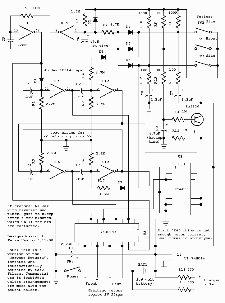
For those confused by my ascii-art diagrams, here's a drafted schematic with the timer and feeler layers in place. The drawing was created by DesignWorks lite (www.capilano.com), printed to a postscript file, copied to clipboard using Ghostview then pasted into L-View to make a GIF file. Hopefully the text is still legible enough...
Touch Sensors and An Activity Controller...
Here's one thing that could be done with the extra trigger... when powered on the robot walks for a period then shuts down until something touches one of the feelers then it comes alive and repeats the cycle. The 1.5 meg and 47uF determine the on-time, the 4.7K sets wakeup sensitivity (also how much it lengthens 'on' time when running into stuff). Also shown is the feeler to neuron interface, the 4.7 meg resistors connect to the 2.2 meg neuron resistors for the front motors, vary the resistor size for different effect. Resistor values more-or-less guessed at, subject to change. Different chip families (probably) produce different times for a given R/C, throw it together to see where it's at then alter values as needed.
                         .-- +
   left    .-- 100K -----*----- 100K --.  right
   feeler  |                           |  feeler
   switch  |        2.2u   2.2u        |  switch
      O----*-- 100 --||--*--||-- 100 --*----O      vary the 1.5M to
     \     |        +   _|_   +        |     /     change 'on' time
      O    |                           |    O      .
     _|_   *-|<|-- 4.7M ----> (2)      |   _|_    .  +
           |      (4) <--- 4.7M --|>|--*         .   |   existing starter,
           |                           |  .----|>|---*   but run 10Meg as
           `--|<|----*------------|>|--'  *-- 1.5M --'   shown, not to +
  from               |                    |  1|\ 2           13|\ 12
  front   >---|<|----*----- 4.7K ---------*---| >O--- 10M --*--| >O--
  feeler                                 _|_+ |/           _|_ |/
  switch   (2),(4) - to inputs of    47u -.-  extra        -.- .22
                    front neurons        _|_  trigger      _|_
Sometimes the robot gets hung up on something with the feelers with the front feeler clear, there until it times out. This layer engages reverse if either the left or right feeler contacts too much, increasing its ability in a cluttered environment.
                           +
                          e|
     <--|<|--*-- 1.5M --b|< pnp     .--- 22K ---|>|----*---> to
             |            c|        |                 c|     reverse
     <--|<|--'             `-- 1M --*--- 1M -----*--b|< npn  switch
                                   _|_+          |    e|
    to L/R                    2.2u -.-  .- 470K -'     |
    feelers                        _|_ _|_            _|_
To alter response time, change the size of the 2.2uF capacitor or the 1M resistor from the pnp collector. The transistors are the common 2N3904 and 2N3906 type, diodes are 1N914/1N4148 type.
The most critical components are the gearmotors, these need to be about 30 rpm at about 3 volts, preferably drawing less than 100ma or you'll have drive problems. The gearmotors I used are not that efficient and need three stacked 245 chips to drive them, but I don't care because they saved me tons of time not having to fool around with gears, unfortunately the supply of them is no more. The PiTronics site lists gearmotors on the "spider parts" page, I've seen various other gearmotors and gear kits at some of the other hobby robotics sites, look around. Another alternative is to take the electronics out of hobby servos, convenient since they have mechanical stops built in, but to use them you might have to up the voltage to 4.8 volts (instead of the 3.6 volts I have indicated) if the motors don't run fast enough.
Some components (particularly the 2.2 meg resistors in the microcore) might need tweeking to match the motors you get, be prepared to swap out resistors and stuff to get it walking just right. For trimming you'll need very high value resistors on the order of 20 to 60 megs or more, series what you have. If you use resistors and capacitors matched to 1% in the microcore you might get away with not having to tweek. A cool way to do it if you have the room is to put trimpots in series with the 2.2 meg core resistors and dial it in exactly.
This is an approximate list of the parts in all of the layers so far...
2 - gearmotors, 30 rpm 3 volts at about 90ma (less current would be
better)
1 - cylindrical 220maH 3.6 volt nicad cordless phone battery
1 - SPST switch to use for power on/off
1 - 74HCT14 chip (74HC14 works better I hear)
3 - 74HCT245 chips (74HC245 is better... use 1 per about 30ma motor current)
1 - CD4053B chip (any 4053 probably ok)
10 - 1N914 or 1N4148 type diodes
1 - 2N3904 type transistor, NPN
2 - 2N3906 type transistors, PNP
1 - 47uF capacitor (walk time)
1 - 4.7uF capacitor (backup time)
4 - 2.2uF capacitors
1 - 0.22uF capacitor, 5% poly
4 - 0.1uF capacitors, 5% poly
3 - 100 ohm resistors (all resistors 1/4W if possible, otherwise 1/2W)
2 - 330 ohm resistors (for the charging adapter, typically 9 to 12 volts
DC)
1 - 4.7K resistor
1 - 22K resistor
2 - 100K resistors
1 - 470K resistor
5 - 1M resistors
2 - 1.5M resistors
4 - 2.2M resistors (microcore rhythm speed)
2 - 4.7M resistors (feeler steering sensitivity)
1 - 10M resistor
also...
perfboard, wire for legs and frame, springy wire like guitar strings for feelers, an assortment of high-value resistors for tweeking, 10M, 15M, 22M, 33M if you can find them, or use 200K trimmers in series with the 2.2M microcore resistors for dial-in tweaking.
Forgive me if I missed anything.
Here are some useful Digikey part numbers...
Resistors...
1/4 watt carbon 5% = value + "QBK-ND" as in 1.8MQBK-ND

Capacitors...
(5% V series)
 .1uF    P4525-ND
 .22uF   P4667-ND
(radial SU series)
 2.2uF   P6261-ND
 4.7uF   P6247-ND
  47uF   P6238-ND

1N914/4148 type Diodes  1N4148DICT-ND

Chips...
 '14     MM74HC14N-ND
 '245    MM74HC245AN-ND
 '4053   CD4053BE-ND

Transistors...
 NPN     2N3904-ND
 PNP     2N3906-ND
Because of the reverser circuit, you can't connect feedback resistors to the front drivers unless they are 4.7K or more (too high to be effective in my opinion), but lower values down to 470 ohm can be connected from the front motor outs directly to the microcore. Connect two resistors between '4053 pin 4 and '245 pin 12, and between '4053 pin 15 and '245 pin 14. If the activity timer shown above is used, feedback on the rear motors (from '245 pin 3 to 18 and from 4 to 16) will slowly discharge the battery when sleeping. To use rear feedback with a sleep mode, some other kind of timing mechanism should be used, something that doesn't hold one input high (making the out low, completing a path through the feedback resistors when it's supposed to be off), like the coded-timer portion of the PIC brain.
The effects of feedback are complex and controversial. Try it, if you like it keep it, otherwise there are lots of other adaptive mechanisms to keep you busy without direct electrical feedback. Previous experiments indicate timing changes on the order of 5%, small in comparison to sensor connections that might change it 30% all but swamping the feedback effect. I like the idea of more possibility, so I have feedback on the front. Does it do any good? Who knows.
The associative memory section has been removed from this page, changes too much. Refer to Brain Transplant for a programmed PIC brain, or the bitnet section of Walker Brains for a simple hardware version. The PIC worked better, the hardware net made me feel better but needs to be simplified parts-wise, but to make sure I remain balanced it's fixing to be back to hard-wired control like it was.
Last modified June 23, 1998
Send comments/questions to Terry Newton, wtnewton@nc5.infi.net