A Self-Programming Autonomous Robot
by Terry Newton, November 1996
This is an ongoing project to explore simple learning algorithms by incorporating
them into a small toy "Spider" robot. Although not specifically
programmed to do anything, it learns through experience to make moves and
seek conditions that satisfy pre-programmed conditions. In other words,
I don't tell it HOW to avoid obstacles in its path, all I tell it is that
objects in its path are not desirable. It has to discover the proper solutions
through trial and error then remember the correct responses.
The Three Classes of Machine Intelligence
Many of the ideas I'm using here come from a 1979 book entitled "How
to Build Your Own Self-Programming Robot" by David L. Heiserman (TAB
books number 1241). He describes three levels of machine intelligence.
Taken from the book, these are:
"An Alpha-Class robot is one whose responses are limited to basic
reflex activity. One can include any number of sensory systems to sense
light, sound, touch, and so on, but the responses are purely reflexive,
and for the most part, random in nature."
"A Beta-Class robot is slightly more intelligent than any Alpha-Class
version. Beta robots have the same primitive reflex mechanisms, but they
are also able to remember reflex responses that work best under a given
set of circumstances. So whenever a Beta-Class robot manages to extricate
itself via a set of random responses from an undesirable environmental
condition, it remembers the one response that worked and then uses it immediately
whenever the same situation arises again. The responses are purely reflexive
and random the first time around, but they become more rational as the
machine gains experience with the world around it."
"A Gamma-Class robot includes the reflex and memory features of
the two lower-order machines, but it also has the ability to generalize
whatever it learns through direct experience. Once a Gamma-Class robot
meets and solves a particular problem, it not only remembers the solution,
but generalizes that solution into a variety of similar situations not
yet encountered. Such a robot need not encounter every possible situation
before discovering what it is supposed to do; rather it generalizes its
first-hand responses, thereby making it possible to deal with the unexpected
elements of its life more effectively."
A Simple Implementation of an Autonomous Robot
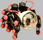 The robot kit used as a
chassis for the experimental circuitry comes from OWI, model MV-962. The
robot has six legs driven by two motors using a crank mechanism. The stock
kit isn't very smart, it merely turns whenever it encounters an object
with its infrared sensor. Call OWI Inc. at (310) 638-4732 for ordering
information or visit their web site at http://www.owirobot.com/.
The robot kit used as a
chassis for the experimental circuitry comes from OWI, model MV-962. The
robot has six legs driven by two motors using a crank mechanism. The stock
kit isn't very smart, it merely turns whenever it encounters an object
with its infrared sensor. Call OWI Inc. at (310) 638-4732 for ordering
information or visit their web site at http://www.owirobot.com/.
By adding a few more senses, a microprocessor and some non-volatile
memory it now has the ability to learn from its surroundings and make "correct"
responses triggered by its environment. The processor I used for the new
"brain" is a PIC16C54 chip with 512 12-bit words of programmable
ROM, 32 bytes of RAM and 12 I/O lines. If the code exceeds the capacity
of this chip the PIC16C56 chip provides 1K words of ROM. For pattern storage
a 24C65 EE-prom chip provides 8 kilobytes in an 8 pin package. A simple
555 counter chip is wired to the Real Time Counter input to provide a simple
way to obtain random responses when required. Refer to the end of this
file for circuit details.
In addition to the forward-looking infrared sensor that came with the
kit, I added two photocell 'eyes' and provided feedback from each motor
to indicate stall conditions. The photocell eyes are wired to respond to
differences in light rather than absolute level. Normally they only detect
three conditions: same light on both, shadow on the left and shadow on
the right, but by taking two readings then combining them a fourth condition
representing motion can also be detected. Together, the environment is
presented to it as 7 bits of information, six are currently being used.
To drive the motors three signals are provided, Left Drive, Right Drive
and reverse. Currently only the left motor is reversible, using a relay.
Four levels of speed are available for each motor using pulse-width modulation,
so internally the response is stored as 5 bits, 2 for each motor plus the
reverse bit.
The EE-prom interface takes up the processor's remaining 2 I/O lines,
maxing out the 18 pin PIC chip. One of the unused inputs is borrowed for
an LED to indicate the creature's state of mind.
The Algorithm
This is an experiment in learned behavior. I do not specifically tell
it what to do, the only programming is defining what makes it happy and
what disturbs it. No specific moves are programmed, these must be acquired
through experience. Normally sophisticated neural networks are used for
this kind of task, but I don't think I can code anything useful using neural
nets in the tight confines of the simple PIC processor I'm using. Rather
a direct approach is used and moves are tagged with a number representing
Confidence. If Confidence is above zero the stored move is used, otherwise
a random move is chosen. When a move works, Confidence is increased up
to a maximum value. If the move did not work, Confidence is reduced down
to zero. The sensor input bits from the current environment (and optionally
the previous environment) are used to calculate the address of the memory.
Here's the basic idea...
Read ThisEnv from sensors
Copy ThisEnv to LastEnv

MainLoop:
 Form Address from ThisEnv and LastEnv (or use only ThisEnv as address)
 Copy ThisEnv to LastEnv
 Access EE memory and get Action and Confidence
 If Confidence = 0 then:
   set Action to random
   set Confidence = 1 (or just leave 0)
 Perform Action (drive the motors)
 Read ThisEnv from sensors
 Evaluate move - is the robot "happy"?
 If good move:
   If Confidence = maxconfidence then goto MainLoop
   Increment Confidence (by 1 or 2) up to maxconfidence
 Else: (bad move)
   If Confidence = 0 then goto MainLoop
   Decrement Confidence down to 0
 Store Action and Confidence into EE Address
 If Confidence = maxconfidence then goto Gamma
Goto MainLoop

Gamma:
 Loop Address through every EE memory location
  AND lowest bits of Address with LastEnv
  If any bits in common then:
    Read Confidence from EE Address
    If Confidence = 0 then:
      Confidence = 1 (or more)
      Write Action and Confidence to EE Address
 Do next Address
Goto MainLoop
PIC code implementation
The current PIC implementation of the algorithm
goes much further than this simple outline. Many of the variable aspects
of the algorithm (or the parts I wasn't sure about:) are tied to a Program
Flow Control Register, a collection of bits that determines the flow through
the program code, altering both variables and the algorithm itself. Some
versions associate memories with only the current environment, others consider
now and then when identifying memories. Some versions use the gamma code,
some use a variation that not only generalizes good moves but bad moves
also. As listed, if the robot a certain number of bad moves in a row it
randomly changes the Flow Control Word in the hope that something else
might work better. If desired self-modification can be disallowed and the
algorithm options set manually.
Behavior stems not from telling the robot what to do, but rather specifying
what output conditions are acceptable and what input conditions are to
be avoided. How to avoid unacceptable environment conditions is not specified,
rather it has to learn through trial and error the output moves that result
in favorable conditions. The following code fragment illustrates how behavior
is (not) specified:
MotorL1  = 7            ; define Action (motor) bits...
MotorL2  = 6
MotorR1  = 5
MotorR2  = 4
MotorRev = 3

; acceptable 'normal' output states...
Goal0 = 10100000b       ; forward slow
Goal1 = 01010000b       ; forward medium
Goal2 = 11110000b       ; forward fast
Goal3 = 11010000b       ; fast forward and right
Goal4 = 01110000b       ; fast forward and left
Goal5 = 11100000b       ; turn right
Goal6 = 10110000b       ; turn left

; environment bits...
L_Shadow   = 0          ; high when shadow is on the left
R_Shadow   = 1          ; high when shadow is on the right
L_Stall    = 2          ; high when motor is drawing excessive
R_Stall    = 3          ;   current indicating a stall condition
IR_Obj     = 4          ; low when IR detects an object ahead
Feeler     = 5          ; Forward-facing touch switch (added 11-6)
Sense6     = 6          ; (extra) active low, doubles as LED out

EnvMask    = 01111111b  ; mask of available environment bits
ALMask     = 01010000b  ; mask of active-low environment bits

; unacceptable environment bits...
InhibA = 00111100b      ; IR, stall or feel - for normal conditions

; unacceptable environment after so many bad moves...
InhibB = 00001111b      ; stall or photo - plan B (go to the light)
The various goal and inhibit masks determine what the robot likes and
doesn't like, the result of the evaluation is a single good/bad flag, telling
the robot to either strengthen the confidence of the last memory or to
weaken it. When the environment triggers a memory with zero confidence
it picks a move at random. Initially all of the moves are random and result
in a very confused robot, but only for a short period of time. Soon it
learns what it's supposed to do in response to open space, walls and obstacles
in its path without being specifically told what to do.
But what does it do?
Not much, by AI standards it's just plain stupid. However it is definitely
doing something. It can pass the paper-bag test - the first encounter with
a bag might give it some problems but once it learns it navigates out of
the bag with little effort. It passes the "Purring" test devised
by Brian Keeley, the cat thinks it's alive. With a little training it can
learn simple tricks but don't expect much. Mostly it wanders around checking
stuff out and just does its own thing, oblivious of any human expectations
of it.
This I believe is one of the failings of AI research - the expectation
that intelligence means human-level intelligence. We devise artificial
tests to try to quantify intelligence then condemn anything that fails
as not being intelligent. An associative memory like the one described
has no more intelligence than an earthworm, probably less. It is an autonomous
robot, not a person. It doesn't have to explain itself, all it has to do
is get around by itself and react to its environment. In many ways, it
is the environment itself that provides the intelligence, the software
need only provide sensor motor coupling in a way that can be remembered.
Circuit Details...
The circuitry is roughly divided up into five sections; the CPU circuit,
the IR object detection circuit, the photo-sense circuitry, the motor drive
circuitry/power supply, and the circuit that detects if the motors are
stalled or being loaded. The IR circuit was part of the stock kit, the
photo-sense circuitry uses half of the 339 chip left over after removing
the existing motor drive circuitry and assembled onto the back of the stock
circuit board. The designations A0, A1, B0-B4, B6 and B7 refer to the PIC
port pin connections to the CPU circuit. Input B5 is not used, tie to ground.
Motor Drive Circuitry / Power Supply...
                                 .----------> 9V
          power                  |                       .-----.
+ .---------O->O-----------------o-----------------------|7805 |----> 5V
__|__     switch                 |                       '-----'  short wire
 ___  + .---O->O---o---o----------------------------o---.   |     to brain board
_____ __|__      Q1|   |         |                Q2|   |  _|_    .1uF on 5V line
 ___   ___      e|/p   |         |               e|/p   |
  |9V _____   .-b| n  _|_        |             .-b| n  _|_
 _|_   ___    | c|\p  /_\        |             | c|\p  /_\
        |3V  _|_   |   |         |            _|_   |   |
       _|_  |   |  o---'         |           |   |  o---'
            |100|  |  .--------- | ---.      |100|  |     Q1,Q2 - TIP42 PNP
            |_ _|  |  |relay  .--o    |      |_ _|  |     Q3-Q5 - PN3568 or
              |    O  O  O    O  |    |+       |    |+      any small NPN
              |     `--. |      _|_ left       |  right   Relay - Digikey Z824-ND
            Q3|    ,--- \`      /_\ motor    Q4|  motor   Diodes - 1N400x type
           c|/n    O  O  O    O  |    |-    c|/n    |-
        .--b| p    |  |       `--o    |  .--b| p    |
       _|_ e|\n    |  `--------- | ---` _|_ e|\n    |
      |   |   |    o-------.    _|_    |   |   |    o----.
      |2.2|  _|_  _|_      |   |   |   |2.2|  _|_  _|_   |
      |_K_|      |   |     |   |47 |   |_K_|      |   |  |
        |        |.47|     |   |_ _|     |        |.47|  |
        |        |_ _|     `---- | ----- | ---.   |_ _|  | To stall-sense
        |         _|_         c|/n       |    |    _|_   | circuitry
        |                 .---b| p       |    |          `---> B
        `------------.   _|_  e|\n       |    `--------------> A
                     |  |   | Q5_|_      |
from brain board     |  |1K |            |
 L Drive   A0 >------'  |_ _|            |
 R Drive   A1 >---------- | -------------'
 L Reverse B7 >-----------'
Stall Sense Circuitry...
 9V >----o-------------------o-----------.
        _|_                  |         __|__ +
       |   |                 |         _____ 2.2u
       |33K|            LMC6482          |
       |_ _|            (rail-rail)     _|_
         |                 _ |                    pulse stretchers
         o-----.          | -|
   1N914_|_   _|_   A >---|+  -_    .-----. 1N914          .-----.
       _\_/_ |100|        |    _----|470  |--|>|--o-----o--| 22K |--> B2
        _|_  |KT |<---o---|- _-     `-----'    +__|__  _|_ `-----'    L Stall
             |_ _|    |   |_-                   _____ |   |
            / _|_     |                     2.2u _|_  |4.7|         to brain
           |          |    _                          |_K_|          board
         stall        |   | -_                         _|_
       sensitivity    `---|-  -_    .-----. 1N914          .-----.
         adjust           |    _----|470  |--|>|--o-----o--| 22K |--> B3
                    B >---|+ _-     `-----'    +__|__  _|_ `-----'    R Stall
                          |_-|                  _____ |   |
                             |              2.2u _|_  |4.7|
                            _|_                       |_K_|
                                                       _|_
Photo-Sense, IR and other circuitry...
 9V >-----o------------------------------o-----o---o---> 9V to IR
         _|_                            _|_   _|_  |     circuits
        |   |                          |   | |   | |   (part of OWI
        |22K|                          |22K| |22K| |    MV-962 kit)
        |_ _|                    _     |_ _| |_ _| |
          |   .-----.           | -_     |     |   |
          o---| 22K |---o-------|-  -_   |     |   |
  left    |   `-----'   |       |    _---o---- | -------> R Shadow
  photo __|__     .---- | ------|+ _-          |   |      B1
  cell |     |    |    _|_      |_- 1/2 339    |   |
       |__ __|    |   |   |        (left over  o--------> L Shadow
          |       |   |4.7|      _ from stock  |   |      B0
          |       |   |_K_|     | -_ circuit)  |  _|_
          o-------o---- | ------|-  -_         | |   |    to brain
  right   |             o---.   |    _---------' |27K|     board
  photo __|__          _|_  `---|+ _-            |_ _|
  cell |     |        |   |     |_-                |      ______
       |__ __|        |22K|         IR Object >----o----> IR OBJ
          |           |_ _|         detect out            B4
         _|_           _|_         (339 active low)

                   ^^     .-----.
from brain >-------|<|----|2.2K |-------< 5V
 board  B6     "sad" LED  `-----'


              | O------< 5V
            |-|         .-----.
              | O--|>|--| 470 |---o------o----> to brain
     Feeler       1N914 '-----'   |     _|_     board  B5
     Switch                    +__|__  |   |
                           2.2u _____  |68K|
                                  |    |_ _|
                                 _|_    _|_
Brain Board Circuit...
Code Notes Section
The last code change (today 11/11/96) did away with the InhibI mask,
the bits that if present in the previous environment relaxes the Goal states.
Rather the InhibA and InhibB masks are used, whichever is in force. InhibI
was set so any stimulus relaxes the rules but it learned a few bad habits,
like sitting there clicking its relay with no motion and being perfectly
happy about it. This annoying behaviour wasn't obvious at first then it
discovered it could get away with it. The new code ignores the rules only
if the previous environment contains an inhibiting bit of the plan in effect
and results in stabler behavior.
The flow of execution is controlled by a collection of flags, the Program
Flow Control Word. One of the bits disallows self-modification allowing
specific algorithm variations to be studied, otherwise after a specific
number of bad moves in a row it reloads the flags randomly, forcing a "mood
change". Another kind of mood change (also after a particular number
of bad moves in a row) is shifting the inhibit bits from InhibA to InhibB.
Plan A is normal obstacle avoidance, while plan B results in a kind of
photo-axis response and remains in effect for so many moves then plan A
takes over again. A neighbor was witnessing an unsuccessful encounter with
a small bag and suggested that it should ignore IR and go to the light
instead in situations like that. Seems to work. Refer to the source code
for detailed descriptions of the various constants. Some of the events
are keyed to a bad-moves counter by bit change, the constant 3 changes
when the count hits 9 (1000=bit 3 just went high).
Minor changes 11-15, reduced number of confidence values from 8 to 4
(changed a 1 to a 0 in a mask) - seems to learn faster now. 4 was the original
number but I was messing around, making it 8 was fun but 4 seems better.
Cool, that's another action bit if I want it, like for reversing the other
motor. Imagine if you could only turn one way? It wouldn't be fun. At least
this thing is too dumb to complain, it just makes use of the facilities
it has.